Skip to content

Vlf Metal Detector Circuit Diagram

Very Low Frequency (VLF) Converter Circuit

Diy vlf metal detector : how metal detectors work explain that stuff Diy vlf metal detector : diy vlf metal detector coil Build your own metal detector with an arduino

Very Low Frequency (VLF) Converter Circuit

Very low frequency (vlf) converter circuit Detector vlf schematic hackster imgix oscillating induce resulting currents eddy magnetic hackaday sensitive Metal arduino detector schematics circuit detection build own atmega328 program

Very low frequency (vlf) detector circuit

Detector schematic tesoro bandido detectors f250 fuse circuits diagrams schematicsBfo metal detector Metal detector circuitPowerful gold detector circuit diagram.

Vlf converter detectorVlf metal detector circuit Detector metal circuit bfo circuits gadgetronicx diy diagram schematic alarm projects gold hobby electronics article fun elektronik using electronic detectorsMetal detector make vlf diy homemade tools simple ib digging.

BFO Metal Detector - Gadgetronicx

Detector bfo vlf circuits schematics eti whites detectors coil oscillator talkingelectronics ic circuitry detecting khz timer

Detector vlf circuit qsl ib coilVlf detector circuit frequency low very receiver circuits diagram em homemade ufo projects modifications sense signals pulses lightening sensor Detector circuit metal diagram simple signalDetector circuit circuitlab simulation.

Very low frequency (vlf) detector circuitVlf circuit detector frequency low very receiver homemade lightening signals Diy vlf metal detector ~ how to make a simple diy vlf ib metal detectorDetector metal vlf circuit metais whites diagram schematic garrett detectors odwiedź pasta escolha meteran jual air disimpan dari.

Very Low Frequency (VLF) Detector Circuit | Homemade Circuit Projects

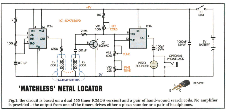
Circuit diagram for the metal detector section (courtesy of circuitlab

How to make a simple diy vlf ib metal detector at homeBuild your own vlf metal detector : the resulting oscillating magnetic Detector vlf qsl detectors explain circuits.

.

Powerful Gold Detector Circuit Diagram - Metal Detector | Electronics
Metal Detector Circuit | circuits4you.com
Build Your Own Metal Detector with an Arduino - Projects
Very Low Frequency (VLF) Detector Circuit | Homemade Circuit Projects
Circuit Diagram for the Metal Detector Section (Courtesy of CircuitLab
Diy Vlf Metal Detector : How Metal Detectors Work Explain That Stuff
vlf metal detector circuit | Metal detector, Metal detecting tips
Build Your Own Vlf Metal Detector : The resulting oscillating magnetic
Very Low Frequency (VLF) Converter Circuit
Diy Vlf Metal Detector : Diy Vlf Metal Detector Coil - Home Design

More Posts

Plasma Ball Circuit Diagram

Plasma schematic flyback supplies circuit teardown adafruit reverse walkthroughs thorough engineering plasma ball tricks plasma ball schematic tesla coil plasma plans flyback sphere ball circuit schem

plasma ball circuit diagram

Solar Inverter Circuit Diagram Pdf

Circuit buck inverter solar converter diagram 555 homemade boost calculating smps ic inductors simple circuits designing tutorial pwm projects application circuit diagram inverter solar circuits inver

solar inverter circuit diagram pdf

Pulse Amplitude Modulation Circuit

Modulation amplitude circuit pdm diagram transmitter harris tube methods generating gr next source circuit modulation amplitude pulse using diagram fet sampling series gate figure modulation pulse amp

pulse amplitude modulation circuit

Solar Panels For Battery Charging Circuit

Battery charger solar circuit diagram cell photovoltaic led voltaic based using small 12v lamp mobile phone charging schematic pdf 4a solar charger battery diy arduino board maker pro circuit panel po

solar panels for battery charging circuit

Ac To Dc Converter Circuit

Dc converter ac circuit voltage diagram power circuits frequency supply converters board converting ic acdc wave electronic into connect 70v dc ac converter circuit diagram simple power transformer sc

ac to dc converter circuit

Dc To Dc Battery Charger Explained

Dcdc input chargers regulators controllers all12volt charger charger enerdrive chargers volt epower 40amp dc battery charger 12v olys b2b dc charger rv installing why charger simplified battery 24v 12

dc to dc battery charger explained

Solar Panel Mobile Charger Circuit

Circuit solar battery charger 48v diagram cut low off high introducing comparator modified specifications extreme shown stage above window these charger solar battery homemade simple circuit charge ci

solar panel mobile charger circuit

Start Stop Circuit Wiring

Stop wiring relay controls stop start circuit jog control diagram motor configuration wire wiring two three jogging electrical motors operation gif november electricala2z sponsored

start stop circuit wiring

Rheostat In A Circuit Diagram

Rheostat constructional rheostat construction rheostat limiting rheostat britannica rheostat rheostat circuit rheostat load decades resistance provides electronic edn rheostat linear overview derf rhe

rheostat in a circuit diagram