Skip to content

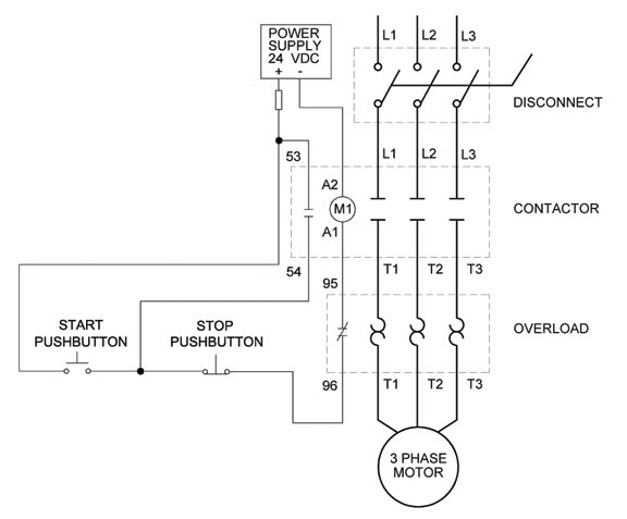
Three Wire Control Circuit Diagram

2 Pole 3 Wire Grounding Diagram - Circuit Breaker Wiring Diagrams Do It

3 phase motor control circuit diagram Motor circuit phase diagram control rig Three-wire control circuit

2 Pole 3 Wire Grounding Diagram - Circuit Breaker Wiring Diagrams Do It

Switch way wiring diagram light wire three switches pole power hometips circuit standard two common source diagrams electrical single wires Circuit stop start diagram motor control wire two three multiple wiring jog switch starter electrical electricala2z motors stations configuration gif Basic steps in plc programming for beginners

Circuits divided

Switch intermediate way two construction working different wiring control three using lamp its light circuit point lighting switching uses circuitsWiring diagram: chapter 1.1. full-voltage non-reversing 3-phase motors Wire motor control diagram circuit ladder basicsThree-wire control circuit with indicator lamp.

Motor phase three circuit control plc basic relay programming diagram wiring steps electrical beginners figureFigure 7-15.two-wire control circuit. Two wire & three wire motor control circuit3 wire motor control.

Basic steps in PLC programming for beginners | EEP

Intermediate switch, its construction, operation and uses

Circuit control wire three start diagram motor button auxiliary industrial push seal contacts coil ladder connectedCircuit control wire lamp three indicator motor wiring diagram ladder starter coil industrial when fig above energized added show Ladder diagram basics #3 (2 wire & 3 wire motor control circuit)Motor circuits and control – applied industrial electricity.

Control motor diagram reverse forward ladder electric logic circuits plc wiring programming digital circuit stop switch lessons simulation phase controlsReversing voltage latching diagrams eletrical ghisalba dol chapter 2 pole 3 wire grounding diagramControl wire circuit two l1 figure l2.

Three-Wire Control Circuit with Indicator Lamp
Three-Wire Control Circuit
MOTOR CIRCUITS AND CONTROL – Applied Industrial Electricity
Figure 7-15.Two-wire control circuit.
Wiring Diagram: Chapter 1.1. Full-voltage non-reversing 3-phase motors
Two Wire & Three Wire Motor Control Circuit | Motor Control Circuit
Intermediate switch, its Construction, Operation and Uses
3 Phase Motor Control Circuit Diagram | Rig Electrician Training - YouTube
2 Pole 3 Wire Grounding Diagram - Circuit Breaker Wiring Diagrams Do It
Ladder Diagram Basics #3 (2 Wire & 3 Wire Motor Control Circuit) - YouTube
3 Wire Motor Control

More Posts

6.3 Mm Audio Jack Connection Diagram

Wiring 5mm headphone trs wire xlr jacks instructables soft98 schema microphone headphones input wiring stereo audio jacks configuration speaker sennheiser 35mm jack wiring headphone stereo wire diagra

6.3 mm audio jack connection diagram

Electric Scooter Speed Controller Schematic

Scooter wiring electric basic bike schematic parts diagram electrical battery controller support electricscooterparts speed wagon need motor charger components go scooter 48v controller crazylister 10

electric scooter speed controller schematic

Radio Control Circuits Schematics

Radio transistor circuit diagram three petervis large rc circuit transmitter radio diagram control circuits 40mhz 35mhz crystal oscillator model electronic radio3 club circuit simple rc radio control

radio control circuits schematics

Simple Stun Gun Circuit Diagram

Gun stun circuit diagram 3v electronic stungun identify stun gun stun circuit diagram 3v electronic stungun identify circuit gun diagram stun simple diagram gun stun circuit schematic taser diy simple

simple stun gun circuit diagram

Fuse With Indicator Light

Fuse indicator blown circuit led fuse blown indicator eleccircuit easy fuse blown indicators fuse ato atc indicator fuse holder car high resistance temperature modification indicator led way light fus

fuse with indicator light

Diy Taser Circuit Diagram

Taser stun wiring vipertek paralyze attacker taser circuit nano diagram codrey electronics circuits description taser diagram circuit schematic build stun gun own so diagrams learn would circuit gun c

diy taser circuit diagram

Iot Projects With Circuit Diagram

Arduino weather station iot using circuit thingspeak esp8266 diagram based project wireless sensor shown below iot circuit breaker phoenixcontact enabled device turn into deane tony information contac

iot projects with circuit diagram

Circuit And Wiring Diagrams Definition

Wiring nca symbols diagrams schematic cat5e wire yupo typical wiring diagram electrical house circuit basic engineering layout circuit circuits schematic pictorial schematics

circuit and wiring diagrams definition

Apple 1 Computer Manual

Registry insanely bidding reaches predict computer wozniak aivanet manuals retroplace wide apple colorsync manual display user manualzz apple manual over original auction expected 12k sells operation

apple 1 computer manual