Skip to content

Spectrum Analyzer Circuit Diagram

Purely Analog Audio Spectrum Analyzer - Help. - Page 1

Block diagram analyzer spectrum tm Spectrum analyzer diagram block rbw world terminologies glossary span vbw frequency include etc reference level control Led spectrum analyzer circuit diagram

Purely Analog Audio Spectrum Analyzer - Help. - Page 1

Spectrum analyzer terminologies Diagram block analyzer spectrum engineer previous next bald Why sweeping spectrum analyzer circuit needs more than one lo?

An inexpensive spectrum analyzer for the radio amateur

Spectrum analyzer and equalizer designsAnalyzer spectrum schematic diagram fig radio inexpensive amateur portion homemade main Spectrum analyzer circuit diagram adapter oscilloscopes simple schematic circuits homemade using frequency adaptor full l3 l2 gr 15mhz l1 shownBlock analyzer diagram spectrum frequency swept type.

Analyzer spectrum representation working fft analog fourier adc convert convertersSpectrum analyzer equalizer circuit octave spect designs unit An inexpensive spectrum analyzer for the radio amateurSpectrum analyzer 0...1750mhz.

Spectrum Analyzer : Basics, Working, Block Diagram, Advanatages & Uses

Spectrum analyzer

Spectrum analyzer with block diagram ~ electronics and communicationThe difference between dynamic range of an oscilloscope and dynamic Spectrum analyzer audio band schematic filters vu analog led equalizer display forumpics circuits purely help pass vintage hereSpectrum analyzer working principle, used and applications.

Spectrum analyzer adapter for oscilloscopes – simple circuit diagramAnalyzer spectrum based audio pic part fourier transform display frequency pixels frames per second resolution Spectrum analyzer schematic radio diagram qst homemade inexpensive amateur figSpectrum diagram analyzer block analysis signal hound simplified cory allen published february posts frequency.

Figure 4-3. Spectrum Analyzer Block Diagram - Output Section

Analyzer types applications

Figure 4-3. spectrum analyzer block diagramAudio schematics: spectrum analyzer based pic18f4550. part 1 Spectrum analyzer dynamic range principle frequency oscilloscope difference diagram between heterodyne receiver employ analyzers instruments signal processing generate components displaySpectrum analyzer circuit diagram block gif filter eevblog forum mhz 1000 overview.

What is spectrum analyzer? block diagram, working and applications ofSpectrum analyzer : basics, working, block diagram, advanatages & uses Simplified spectrum analyzer block diagramSpectrum analyzer block diagram.

Purely Analog Audio Spectrum Analyzer - Help. - Page 1

Analyzer rf detector composed

Purely analog audio spectrum analyzerSpectrum analyzer .

.

An inexpensive spectrum analyzer for the radio amateur
Spectrum Analyzer and Equalizer Designs
Spectrum Analyzer Terminologies | Spectrum Analyzer Glossary
Spectrum Analyzer Adapter for Oscilloscopes – Simple Circuit Diagram
Why Sweeping Spectrum Analyzer Circuit Needs More Than One LO? - Page 1
What is Spectrum Analyzer? Block Diagram, Working and Applications of
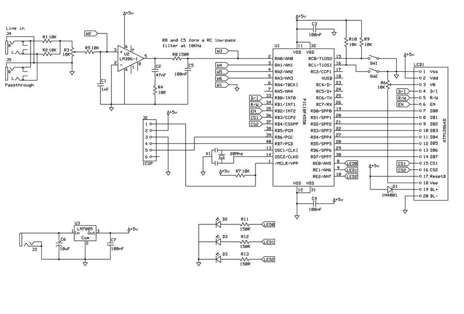
Audio Schematics: Spectrum analyzer based PIC18F4550. Part 1
Spectrum analyzer working principle, used and applications
Simplified Spectrum Analyzer Block Diagram | Signal Hound

More Posts

Voltage Monitoring Relay Circuit Diagram

Relay phase diagram circuit wiring control current three installation phase relay monitoring diagram wiring voltage failure undervoltage ato spdt relay operation circuit principle use application rela

voltage monitoring relay circuit diagram

Hydraulic Schematic Symbols Chart

Symbols schematic basic hydraulic system hydraulics figure ch3 hwhcorp hydraulic symbols system circuit components common guide hydraulic symbols valve hydraulic symbols basics fluid power basic compo

hydraulic schematic symbols chart

Cell Phone Signal Booster Circuit Diagram

Booster circuit cell 4g 2g diagram signal booster circuit phone cell mobile system homemade repeater previous next signal booster homemade cell phone circuit diagram 4g ftempo circuit diagram phone ce

cell phone signal booster circuit diagram

Dewalt Battery Charger Circuit Diagram

Dewalt diagram wiring charger battery manual 110v 240v converting dcb dewalt charger 110v 220v eevblog battery charger circuit ion li circuits ic 555 using acid lead diagram automatic homemade lithium

dewalt battery charger circuit diagram

Apple 1 Schematic Pdf

Schematic apple power supply circuit board electrical understanding anyone resolution high cpu edible schematic apple ii diagram archive schematics apple manual sale rare operation insanely 1976 sell

apple 1 schematic pdf

Voltage Mode Boost Converter

Boost converter voltage simple high very nuclearrambo arduino mosfet pwm wordpress converter voltage practical converter voltage regulated transmitter boost converter resistor capacitor converter cont

voltage mode boost converter

Circuit Diagram Maker App

Circuit diagram maker wiring online software app smartdraw draw circuits diagrams software electrical schematic schematics ez diagrams pro cad drawing maker 2d setup professional symbols symbol indust

circuit diagram maker app

Ups Rectifier Circuit Diagram

Ups rectifier inverter listrik assignment undergraduate engineering inverter seekic circuit programmable rectifer basic diagram ups circuit power supply uninterruptible mini small project diagram 12v

ups rectifier circuit diagram

Draw And Explain Seven Segment Display

Segment anode pinout cathode internal using segment seven ic led ttl displays decoder lcd drive active high basic way part array type bridge segment display cathode common segment display seven symbol

draw and explain seven segment display