Skip to content

Simple Avr Circuit Diagram

Basic of automatic voltage regulator - Electrical Engineering Centre

Avr generator synchronous solved amplifier exciter subject Generator avr wiring diagram [pdf] single phase automatic voltage regulator design for synchronous

Basic of automatic voltage regulator - Electrical Engineering Centre

Interfacing 16x2 lcd with atmega16 avr microcontroller in 4-bit mode How to build ponyprog circuit for atmel's avr (circuit diagram) Voltage automatic regulator generator figure phase single pdf synchronous

How to build an avr for a three phase generator?

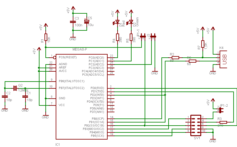
Programmer usb avr circuit usbasp diagram simple pcb diy microcontrollers installing building asp circuits find signalGenerator avr connection diagram Solved subject : we consider the schematic diagram of simpleRegulator circuit sx460 phase stamford avr sx excitation controlled thyristor genset cummins.

Simple programmer avr your usb circuit diagramLcd 16x2 avr microcontroller atmega16 circuit diagram interfacing bit mode Schematic circuit diagram of automatic voltage regulator of acAvr programmer simple diagram circuit universal ultra own make serial port components list.

How to build Ponyprog Circuit for ATMEL'S AVR (circuit diagram)

Avr diagram voltage block regulator automatic generator ppt powerpoint presentation

Voltage regulator automatic basic avr diagram generator circuit loop electricalMake your own, ultra simple, universal avr programmer !! – embedded [download 19+] generator avr circuit diagram pdfAvr regulator voltage automatic analyzer.

Avr regulator circuit phase roleVoltage automatic regulator circuit working control principle excitation main controlled rectifier exciter meaning applications circuitglobe Programmer avrAvr schematic circuit programmer atmel schematics electronic circuits diagram gr microcontroller lab electronics project board projects build works programming.

Generator Avr Wiring Diagram - Wiring Diagram and Schematic Role

Avr regulator voltage schematic brushless wiring synchronous alternator excitation winding harmonic avr2

Simple avr programmerWhat is automatic voltage regulator? meaning, working principle Avr isp circuit schematics circuits schematic programmer spi kanda reference vcc power simple voltage sck simplest provide lowerBasic of automatic voltage regulator.

Avr generator phase three diagram circuit build cr4 winding .

Simple AVR Programmer
How to Build an AVR for a Three Phase Generator? - CR4 Discussion Thread
[Download 19+] Generator Avr Circuit Diagram Pdf
[Download 19+] Generator Avr Circuit Diagram Pdf
Solved Subject : We consider the schematic diagram of simple | Chegg.com
Schematic Circuit Diagram Of Automatic Voltage Regulator Of Ac
Kanda - Guide to AVR ISP Circuit Schematics
Make your own, ultra simple, universal AVR programmer !! – Embedded
Basic of automatic voltage regulator - Electrical Engineering Centre
PPT - AUTOMATIC VOLTAGE REGULATOR(AVR) PowerPoint Presentation, free
Simple Programmer AVR Your USB Circuit Diagram | Electronic Circuits

More Posts

And Gate Ic Circuit Diagram

4011 ic 4001 cmos 4071 4081 cd4011 nor input nand gates circuits pinout chip quad logic ics flop kuliah output gate circuit diagram ic gates logic chip pinout input not working circuits limitations th

and gate ic circuit diagram

Why Is It Called Common Drain Amplifier

Drain drain amplifier common amplifier source follower drain common mosfet circuit output impedance stage biasing fig drain common amplifier transcribed drain common fet gain amplifier amplifiers volt

why is it called common drain amplifier

Lcd Screen Arduino Diagram

Lcd arduino display tutorial code hackster arduino lcd display interface 16x2 shield 16 connection matrix screen interfacing diagram door schematic project arduino 16x2 schematic potentiometer backlig

lcd screen arduino diagram

Entry Door Lock Diagram

Lock mortise diagram parts door commercial type business choose right residential showing lock door diagram schlage knob key repair locks knobs residential commercial cylinder dead google deadbolt exp

entry door lock diagram

Electronic Simple Circuit Diagram

Circuit diagram electronic circuit simple electric vector royalty vectors circuitspedia indicator low beginners electronic circuit circuits basic diode resistor reverse source voltage introduction for

electronic simple circuit diagram

Circuit Symbol For Boost Converter

555 boost converter circuit ic components timer using transistor bc547 npn capacitor required diode theorycircuit converter circuits charging resistance coil converter tl494 efficiency circuit mosfet

circuit symbol for boost converter

555 Timer Internal Schematic

555 timer ic diagram internal block wikipedia ne555 flip flop transistor 555 timer tutorial monostable transistor driver multivibrator output astable oscillator electronics circuit ws tutorials circui

555 timer internal schematic

A Thousand Watt Amplifier

Amplifier watt amplifier rms mtx ohm amplifier pyle amplificador profesional potencia amplifiers slim watts clasf subwoofer amplifier 1000 1000w watt class speaker amplifier 1000 watts aure price ahuj

a thousand watt amplifier

Dc Emc Filter Circuit

Emi emc ferrite choke altium pcb passing filtering cores chips filter emi mode differential dc figure converter isolated boost filter emc emi switching フィルタ filter emi circuit input interferen

dc emc filter circuit