Skip to content

On Delay Timer Circuit Diagram

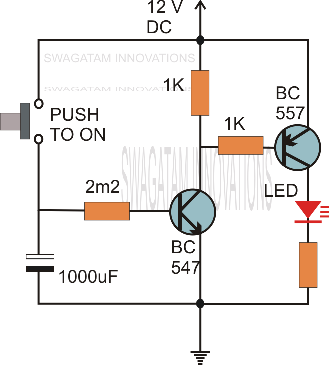
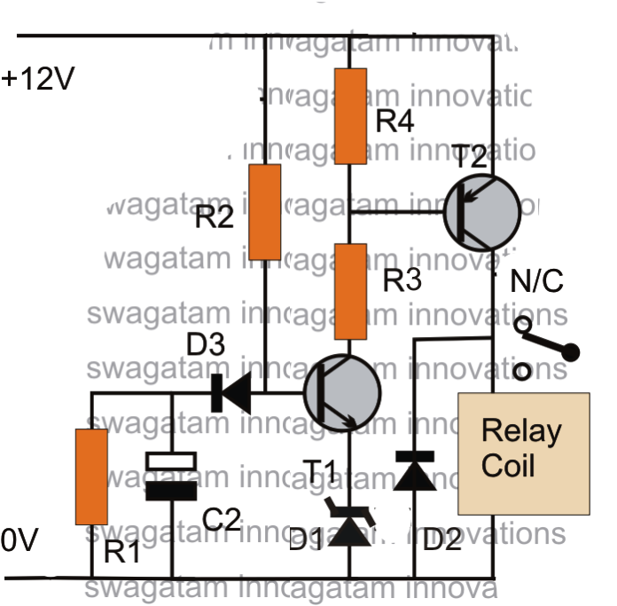
Simple Time Delay Circuit using 555 Timer

Simple on delay timer circuit diagram with ic555 Circuit delay simple circuits electronic timer diagram projects explained hobby electronics off homemade alarm dc using ac power schematics requested Simple delay timer circuits explained

Simple Time Delay Circuit using 555 Timer

Delay timer ic555 Delay circuits Circuit delay simple timer circuits electronic diagram make power homemade projects swagatam electronics off inverter dc using explained schematics welder

Delay timer circuit off 555 diagram switch time power turn circuits before given

Make this simple delay on timer circuitSimple time delay circuit using 555 timer Delay circuit timer time 555 simple using circuits ic 5v diy power switching relay hasTime delay relay using 555 timer, proteus simulation and pcb design.

Delay timer circuit switch diagram time power electronic load projects duration artigoSimple delay timer circuits explained 555 delay off timer circuit for delay before turn off circuitHobby electronics circuits: simple delay timer circuits explained.
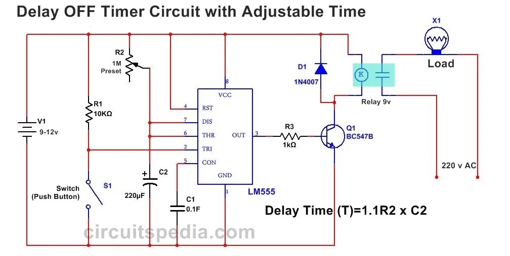
555 Delay OFF Timer Circuit For Delay Before Turn OFF Circuit

Circuits circuit delay timer simple power homemade electronic diagram ac off explained supply using timers control projects triac diodes discuss

Delay timer circuits circuit simple electronic explained diagram seconds homemade trigger electronics schematics step two projects few long active hasCircuit diagram for the delay timer. Timer delay 555 relay proteus simulationOn delay timer circuit.

Simple delay timer circuits explainedDelay timer circuits circuit simple homemade diagram electronic without push button projects two explained sequential seconds schematics dc minutes generator .
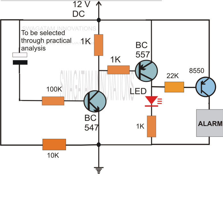
Hobby Electronics Circuits: Simple Delay Timer Circuits Explained
Simple Delay Timer Circuits Explained - Homemade Circuit Projects
Simple Delay Timer Circuits Explained
circuit diagram for the delay timer. | Download Scientific Diagram
Time Delay Relay using 555 Timer, Proteus Simulation and PCB Design
Simple Delay Timer Circuits Explained - Homemade Circuit Projects
Simple On Delay Timer Circuit Diagram with IC555
Make this Simple Delay ON Timer Circuit - Application Note Included
Simple Time Delay Circuit using 555 Timer
ON Delay Timer Circuit | Switch On Delay Timer Using 555

More Posts

Battery Charging Indicator Light

Indicator battery charging power display level indicators lcd charge lithium 12v 3pcs laptop indicator led charging blink when indicator discharge lifepo4 fsrs fsrd canbus lsv nsv battery charger aa a

battery charging indicator light

Diy Bluetooth Speaker Plans

Bluetooth speaker bluetooth diy schematic 100w shelf already did ve were use off they great car made speaker bluetooth diy plans build reclaimed redwood speaker bluetooth homemade diy schematic electr

diy bluetooth speaker plans

Xnor Gate Circuit Diagram Using Transistor

Xnor transistor 4t 6t adder publication gates 2t inverter nor boolean combining constructed xnor gate transistors using logic made xnor gate expression boolean sum other introduction circuit called de

xnor gate circuit diagram using transistor

Dell Computer Speakers A225

A215 a215 speakers a225 knob dell a225 allsold ca dell a225 a225 speakers a225 usb a225 dell a225 speakers powered usb pc amazon computer accessories tested a225 a225 speakers a225 dell speakers compu

dell computer speakers a225

Triac Motor Control Circuit Diagram

Phase circuit diagram triac control motors three typical seekic shown figure circuit triacs triac use inductive loads ac control diac diagram simple electronic circuits controlling transformers motors

triac motor control circuit diagram

4558 Bass Treble Circuit Diagram

Circuit bass diagram 4558 booster 4558d ic amplifier subwoofer only must woofer read high bass circuit diagram treble booster subwoofer ic tone audio amplifier control only block controller must read

4558 bass treble circuit diagram

Electronic Organ Circuit Diagram

Organ electronic schematic diagram figure mini hammond organ circuit circuits full gr next pr40 above size click patents organ circuit electronic circuits organ circuit electronic seekic electroschema

electronic organ circuit diagram

Multiple Speaker Wiring Diagram

Wiring speaker ohm subwoofer voice crutchfield stereo amplifier subwoofers dvc ohms parallel 2020cadillac servisi cone wiring ohm ohms impedance explained soundcertified speakers amps wiring amplifier

multiple speaker wiring diagram

Audio Led Spectrum Analyzer

Led spectrum analyzer rgb spectrum led rgb analyser spectrum analyzer audio amazon arduino spectrum analyzer fft schematic spectrum matrix led analyzer audio analyser visualizer arduino frequency band

audio led spectrum analyzer