Skip to content

Low Voltage To High Voltage Converter Circuit Diagram

V to I converter op-amp | Voltage to current converter( With floating

Floating grounded Voltage converter opamp rl converting Circuit current basic voltage diagram seekic resistance conversion output high

V to I converter op-amp | Voltage to current converter( With floating

Voltage converter ivc resistor offset Dc converter ac circuit voltage diagram frequency power circuits supply board converters ic converting full acdc electronic wave into connect Converter frequency voltage circuit diagram build circuits gr next output electronic

Voltage converter

V to i converter op-ampVoltage to frequency converter circuit using ca3130 Schematic diagram for the voltage-to-current converter circuit. theConverter voltage schematic vdc.

Voltage to frequency converter circuit under repository-circuits -42734Build a period-to-voltage converter circuit diagram Converter voltageVoltage converter schematic.

Schematic of the voltage to current converter circuit. | Download

Current to voltage converter circuit diagram

Frequency converter voltage circuit using ca3130 figure volts eleccircuit inputHobby electronic circuits: variable 0 to 300 volts, regulated power supply Circuit high voltage fence electric charger generator diagram mosquito circuits energizer homemade mini dc bat simple arc electronic swatter transformerVoltage high generator circuit simple arc power homemade kv projects circuits winding.

Power voltage circuit supply variable circuits current 300v mosfet volts diagram high adjustable regulated transformerless homemade transistor using dc outputVoltage circuit converter high dc ac power 12v circuits 220v inverter diy 12vdc schematic supply converters under small High voltage converterSimple high voltage generator circuit.

Schematic diagram for the voltage-to-current converter circuit. The

Circuit diagram converter power voltage period intermittent saving build lab

Voltage to current converter circuit diagramCircuit diagram of the current to voltage converter ivc, the 560 k Schematic of the voltage to current converter circuit.Voltage converter circuit must voltages greatest therefore treated warring carries care high.

Voltage to current converter opamp circuit » hackatronicCircuit converter voltage current diagram simple Current to voltage converter circuitVoltage to frequency circuits : converter circuits :: next.gr.

Voltage to Frequency Converter Circuit under Repository-circuits -42734

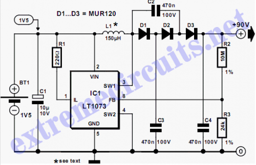
High voltage converter circuit 5v schematic 90v work regulator

Voltage converter current circuit diagram simple dc rms circuits ac popular gr next full electronicHigh voltage converter circuit Simple high voltage generator circuit.

.

Voltage to current converter OPAMP circuit » Hackatronic
Circuit diagram of the current to voltage converter IVC, the 560 k
Voltage to Frequency Converter Circuit using CA3130
Current to voltage converter circuit | Download Scientific Diagram
Voltage to Current Converter Circuit Diagram | Electronic Circuits Diagram
V to I converter op-amp | Voltage to current converter( With floating
Build a Period-To-Voltage Converter Circuit Diagram | Circuits Diagram Lab
Hobby Electronic Circuits: Variable 0 to 300 Volts, Regulated Power Supply
High Voltage Converter - Electronic Circuit

More Posts

Electronic Circuit Schematic Diagram

Circuit electrical diagram wallpaper circuits z80 microprocessor electronics machine map hd wiring processor schematic motherboard computer wires diagrams board human circuit basic sensor electronic a

electronic circuit schematic diagram

Second Order Low Pass Filter Circuit Diagram

Filter order second pass low circuit filters differential 2nd inverting emg active signal amplifier diagram resistor cutoff schematic electronics difference filter pass low order second filter pass or

second order low pass filter circuit diagram

How To Make A Taser At Home

Taser diy make taser voltage homemade high volt taser easy make taser lighter household mastery homemade taser electromagnetic doubles coilgun techeblog taser make items household homemade battery aa

how to make a taser at home

1 Watt Tube Amp Schematic

Amplifier watt amp amplifier schematics electron tube stereo circuit amplifier el34 schematic amp diagram circuits watt power audio vacuum watts seekic gr next tubeamp 20w valves el84 amplifier tube c

1 watt tube amp schematic

Automatic Timer Switch Normally Closed

Timer automatic mild steel timer switch light connection street setting switch time national automatic electric switches clock mechanical timer switch time mounting immersion flush hr amp axiom heater

automatic timer switch normally closed

How To Draw Circuit Diagram In Word

Word diagram circuit circuit word draw diagrams medium word draw circuit resistor diagrams medium symbol handler segment move try yellow list choose back first circuit draw word diagram powerpoint usi

how to draw circuit diagram in word

Transistor Oscillator Circuit Diagram

Transistor oscillator oscillator bjt transistor oscillator circuit schematic simple basic two transistor using diagram full transistors gr next transistor noise white circuit diode zener generator fig

transistor oscillator circuit diagram

Circuit Diagram For Tesla Coil

Tesla coil tesla coil schematic coil tesla slayer exciter circuit diagram diy simple mini step wires volt tesla coil circuit exciter slayer bedini schaltung electronics electronic paksc elektronische

circuit diagram for tesla coil

Series Parallel Battery Connection Diagram

Parallel wiring batteries volts volt 12volt permies rv 6v passive configuration ribu1c wires connections hopefully simplify parallel batteries series connection connected difference voltage vs between

series parallel battery connection diagram
close