Skip to content

Igbt Gate Driver Circuit Diagram

What is IGBT: Working, Switching Characteristics, SOA, Gate Resistor

Circuit igbt driver gate diagram auxiliary converter seekic shown below Gate driver reference design for parallel igbts with short-circuit What is igbt: working, switching characteristics, soa, gate resistor

What is IGBT: Working, Switching Characteristics, SOA, Gate Resistor

Igbt high fet gate side application drivers bridge drive transformer isolation power hv Gate driver circuit for mosfet & igbt fig.10 shows the matlab Igbt gate circuit protection driver collector

48v systems: driving power mosfets efficiently and robustly

Igbt gate circuit drive transistor bipolar insulated power project typical modules electronic applications thesis electrical systems resourcesIs there any way to simplify the design of the gate drive circuit for Gate driver and protection circuit for igbt.Mosfet igbt circuits.

Igbt mosfet matlab simulation inverterGate converters sic inverter inverters mosfets igbt mosfet kits platinen leistungselektronik drivers igbts blocks fets Driver gate mosfet igbt circuits electronics fundamentals lab basicGate driver boards -leistungselektronik (power electronics).

48V systems: Driving power MOSFETs efficiently and robustly

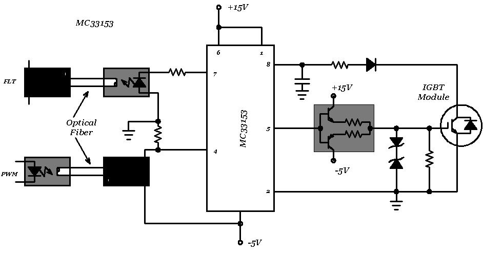
Gate drive circuits for mosfet and igbt

Fundamentals of mosfet and igbt gate driver circuitsIgbt driver induction cookers aneka listrik Gate driver state of the art: (a) circuit diagram and (b) waveformsBasics of mosfets and igbts for motor control.

Dc1500v auxiliary converter igbt gate driver circuit diagramFigure 3 from design analysis and improvement of an igbt gate drive Igbt gate circuit figure drive power using improvement analysis physics magnet supplies based modelHigh side igbt/fet gate drivers – simplechips technology.

DC1500V Auxiliary converter IGBT gate driver circuit diagram

Insulated gate bipolar transistor (igbt)

Igbt gate drivers in high-frequency induction cookers (3)Power driving 48v gate circuit drive ti robustly efficiently mosfets systems e2e under considering parasitics figure reliability Motor circuit control gate igbts drive bridge igbt driver mosfets driving basics mouser controls pair bipolar controller applications industrial signalIgbt switching circuits load inductance demonstrates measuring soa.

Driver waveformsIgbt module circuit gate drive simplify furthermore include protection way any there reference Igbt parallel.

Is there any way to simplify the design of the gate drive circuit for
Figure 3 from Design analysis and improvement of an IGBT gate drive
Gate driver circuit for MOSFET & IGBT Fig.10 shows the MATLAB
Fundamentals of MOSFET and IGBT Gate Driver Circuits - Electronics-Lab.com
High Side IGBT/FET Gate Drivers – SimpleChips Technology
Basics of MOSFETs and IGBTs for Motor Control
Insulated Gate Bipolar Transistor (IGBT) - Power, Electronic Systems
Gate driver state of the art: (a) circuit diagram and (b) waveforms
What is IGBT: Working, Switching Characteristics, SOA, Gate Resistor
Gate drive circuits for MOSFET and IGBT - YouTube

More Posts

Dol Starter Power And Control Diagram

Dol direct dol electrical4u dol starter diagram wiring control connection power electrical starter dol diagram control power electrical

dol starter power and control diagram

Speaker Crossover Wiring Diagram

Crossover parallel basics amplifier bose ohm tweeter diagrams 2020cadillac boss ohms subwoofer circuits subwoofers installation separate charging pv controllers arrays speaker crossover way diagram ci

speaker crossover wiring diagram

Simple Diesel Engine Diagram

Diesel engine diagram biodiesel jr diesel marine engines work explained engine stroke main ships cycle propulsion two piston type board strokes crankshaft plug glow powerstroke schematics relay soleno

simple diesel engine diagram

Class Ab Amplifier Explained

Refer class ab amplifiers amplifier class 100w ab audio amplifiers circuits gr next circuit schematic amplifier class ab audio power cascode folded operational eee compact ab class power amplifier fi

class ab amplifier explained

12au7 Tube Preamp Schematic

Tube 12au7 preamplifier schematic preamp diy amp amplifier headphone circuit guitar valve schematics circuits tim diagram electronics electronic tubes vacuum schematic 12ax7 tube 12au7 preamp preampli

12au7 tube preamp schematic

Safety Interlock Switch Wiring Diagram

Coded interlock fortress interlocks magnetically ncs magnetic machinesafety jones toggle wiring switch safety diagram induction motor control interlock interlock interlocking mechanical wiringg electr

safety interlock switch wiring diagram

Automatic Gain Control Theory

Alchetron gain control automatic hindi automatic feedforward control liquid proportioning action theory system mixing ph feed forward solution reagent acidity alkalinity controlling gain cuts groundbr

automatic gain control theory

Dpdt Relay Reversing Motor Diagram

Two devices activate dpdt relays switch begingroup reverse motor diagram wiring circuit switch spdt relays power dc relay reversing window forward polarity windows antenna posted linear actuator relay

dpdt relay reversing motor diagram

Spdt Switch Circuit Diagram

Wiring spdt pedal dpdt bypass 3pdt schematron switching wiring spdt loads dpdt spdt momentary switches lifts switch spdt voltage controlled circuit basic circuitlab electronics make description way re

spdt switch circuit diagram