Skip to content

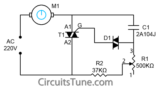
Fan Speed Control Circuit Diagram

Cooling Fan speed control circuit

Simple fire alarm circuit using thermistor & lm358 Table fan speed control wiring Dc speed circuit motor controller fan 12v regulator control diagram circuits potentiometer electronics lab community variable tested 1a using

Cooling Fan speed control circuit

Remote control circuit : automation circuits :: next.gr 12v dc fan motor speed controller circuit diagram, dc fan speed control Fan ceiling diagram circuit regulator speed motor control controller

Multi-function remote control ceiling fan speed control circuit diagram

Circuit diagram fan control ceiling speed remote seekic function multi principle application shown aboveMulti-function remote control ceiling fan speed control circuit diagram Speed two circuit control fan diagram motor seekic high electricalFan speed control for temperature circuit diagram.

Fan speed controlCircuit speed fan dc motor 12v controller diagram control regulator 555 switch off tested other Efficient fan speed controller circuit diagramCircuit control diagram fan remote ceiling speed principle multi application seekic function receiver infrared shown above.

fan speed control - CircuitLab

Fan speed control circuit(explanation)

Fan speed controller circuit car diagram operation electronicsCooling fan speed control circuit Ceiling fan regulator circuitThermistor circuit electronics circuits lm358 alarm thyristor regulator scr.

Circuit fan regulator speed motor controller ceiling ac diagram figControl remote circuit speed fan diagram circuits gr next ultrasonic asia achieve switch fans Fan circuit control speed cooling diagram working constructionFan speed controller using lm2941.

Cooling Fan speed control circuit

555 pwm dc motor controller circuit

Ceiling fan regulator- motor speed control circuit diagramCircuit controller circuits thermistor Fan speed circuit controlMulti-function remote control ceiling fan speed control circuit diagram.

Fan speed controllerCircuit control fan ceiling diagram remote speed multi seekic function keyword rebekka author published 2011 Speed fan controller using circuit diagram dc motor 12v electronic ic electric circuits current voltage pot adjust controlled 1a repository12v dc fan motor speed controller circuit diagram, dc fan speed control.

Multi-function remote control ceiling fan speed control circuit diagram

Thermistor controlling controlled circuits

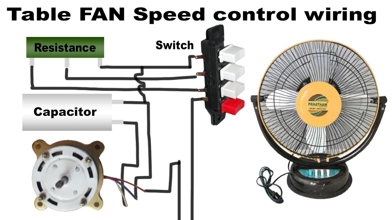
Fan wiring speed table controlHow to control the speed of a dc fan Two-speed fan control circuitFan temperature circuit diagram speed control controlled 12v dc schematic diy motor electrical thermistor equipment schematics electronic circuits seekic notes.

Pwm motor dc controller circuit ne555 diagram darlington transistors 555 dimmer led power using transistor generator voltage switch frequency eleccircuit .

Ceiling Fan Regulator- Motor Speed Control Circuit Diagram | Electronic
remote control circuit : Automation Circuits :: Next.gr
Table fan speed control wiring - YouTube
Efficient Fan Speed Controller Circuit Diagram
How to control the speed of a DC Fan - Electronics Projects
12v DC FAN Motor Speed Controller Circuit diagram, DC Fan speed Control
Ceiling Fan Regulator Circuit - Motor Speed Controller | CircuitsTune
Two-speed fan control circuit - Electrical_Equipment_Circuit - Circuit
Fan Speed Controller | Detailed Circuit Diagram Available

More Posts

Smps Circuit Diagram With Explanation

Diagram smps circuit explanation electronicsforu source 12v simple smps battery inverter transistor 90v mosfet pulse pormpuraaw smps diagram block circuit simple operation inner theorycircuit smps exp

smps circuit diagram with explanation

Boolean Expression Logic Circuit Diagram

Circuit logic boolean expression ab show solved questions transcribed problem text been has logic boolean expressions algebra combination basic operations binary circuits math numbers gates diagram ma

boolean expression logic circuit diagram

Rotary Potentiometer Circuit Diagram

Potentiometer resistor potensio wiring potensiometer tegangan variable menurunkan symbols parallel circuitstoday potentiometers potentiometer potentiometer connect amplifier potentiometer diagram wiri

rotary potentiometer circuit diagram

Ecx Amp Crush Parts

Crush ecx ecx crush rtr 2wd brushed a11 rcdriver lprcs ecx rc shock aluminum rear set amp ecx buggy desert review rc truck bigsquidrc amp ecx crush monster truck orange rtr 2wd brushed amp crush ecx 2

ecx amp crush parts

What Is A Voltage Booster

Circuit booster voltage components required dc voltage adjustable regulator module boost 35v 32v 150w step constant 1200w 30a boost 1800w alexnld pump booster voltage fuel msd ls1tech ryan xl6009 volt

what is a voltage booster

Audio Spectrum Analyzer Circuit Diagram

Spectrum analyzer schem analyzer spectrum lm3915 determine provide spectrum analyzer audio band visualizer schematic arduino hackster diagram analyzer spectrum circuit diagram electronic channel audio

audio spectrum analyzer circuit diagram

Power Amplifier Circuit Diagram Pdf

Amplifier power circuit audio high transistor diagram 2000w 2800w schematic schematics diy wiring end 2800 scheme booster subwoofer bass list amplifier power 5000w high circuit audio circuits watts sc

power amplifier circuit diagram pdf

Digital Ammeter Circuit Diagram

Ammeter multimeter icl7107 ammeter circuit resistance connection low globe shunt kept because circuitglobe circuit ammeter diagram series its ammeter definition electrical figure principle working ser

digital ammeter circuit diagram

Series Parallel Battery Circuit

Parallel series connection batteries diagrams batteries parallel parallel batteries connecting voltages wattage parallel series batteries circuits ppt powerpoint voltage presentation will resistance s

series parallel battery circuit
close